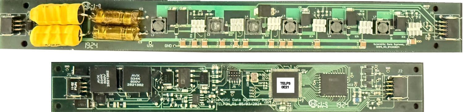
Simple Telemetry Board (STB) and Downhole Power Supply (DHPS) boards.
SDS Downhole Telemetry System
High-speed half-duplex downhole telemetry with 12 to 67 kbps uplink and 1 to 5 kbps downlink. Field-validated for reliable subsurface communication in the most demanding well conditions.
Field-validated and universally compatible. Every SDS product is designed and assembled in Houston, with direct support from the engineers who built it.
Overview
The SDS Telemetry System consists of a Simple Telemetry Board (STB) and an optional Downhole Power Supply Board (DHPS).
The purpose of the STB is to convey data from downhole tools on the tool bus (RS232), Transmit / Receive the data and Commands to / from the surface via a reliable digital telemetry system facilitating communication between the Warrior Surface System and downhole tools.
Typical applications: conventional logging tools (including digital acoustic and spectral data), hybrid tools (telemetry and memory simultaneously), intervention tools (relying heavily on surface to downhole control) and fast mobilization for the development of new tools and sensor testing where 'off the shelf' and simple to setup and interface telemetry can save substantial development time and costs.
STB: Simple Telemetry Circuit Board
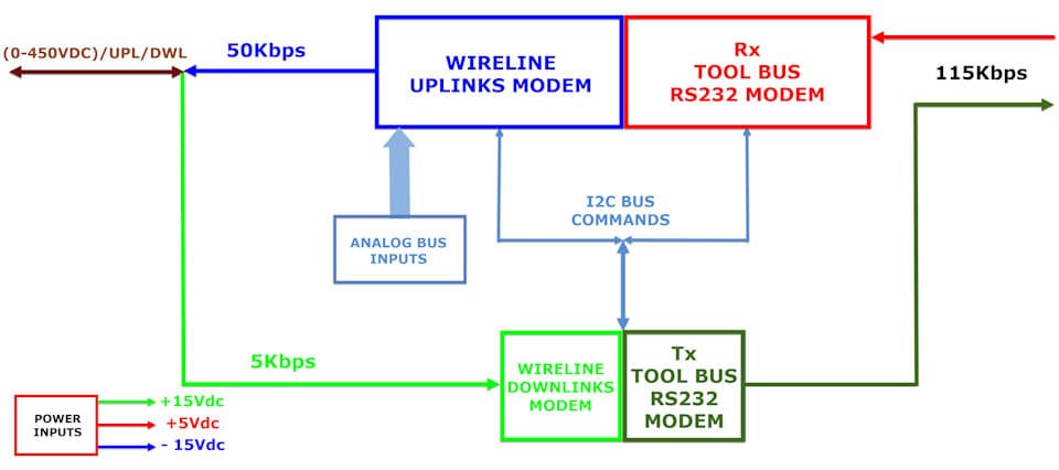
General specifications: Maximum Temperature 350°F (177°C), operating voltages (dependent on power supply) range +0 +450V DC, Current consumption at 200V 15mA, Tool Bus data rate 115kbps, Wireline Uplink data rates currently 12 kbps to 67 kbps, and Downlink rates 1 kbps to 5 kbps. Input Voltage Requirements are typically +15Vdc, -15Vdc and +5Vdc.
STB Functional Blocks
- Wireline Uplink Modem: hardware interface between Rx Tool Bus RS232 Modem and Wireline mono-cable transmitting to surface. Uplinks modulated as pulsed RS232 at 12–67 kbps with ±15Vpk amplitude. Half duplex transmission.
- Rx Tool Bus RS232: hardware interface between downhole tools and Wireline Uplinks Modem. Rx is modulated TTL input (5Vdc), at 115 kbps.
- Wireline Downlink Modem: half duplex downlink allows user to configure and control operations from surface prior to and during logging.
- Tx Tool Bus RS232 Modem: hardware interface between Wireline Downlinks Modem and downhole tools. Tx modulated TTL output to Tool Bus as RS232 at 115 kbps (5Vdc).
- Analog Bus Inputs: receive signals between 0 to 4 VDC. Tool Head Voltage, Internal Downhole Temperature, and Tool Bus Voltage are sensed and sent to the surface to facilitate setting the appropriate operating voltage.
DHPS: Downhole Power Supply
The voltage entering the down-hole system is usually 100VDC, but it can range from 80VDC to 120VDC. To minimize interference with the telemetry signals, a filtering circuit is used. Output voltage: 12V DC with a tolerance of ±0.1V. Maximum current: 250mA. Voltage ripple: 100mV peak-to-peak.
To apply power to the tool, the power supply goes through an unstable transition zone between 10 to 75 volts, where currents of 150 to 250 mA can appear, depending on the load connected at the VOUT (12V) output. Once it passes into the stable zone, the current will be much lower, reaching up to 100V, with 12mA without load at the 12V output or 32mA with load. If the operator accidentally exceeds 130V, the line is immediately disabled to protect the power supply.
A high-efficiency step-down DC / DC regulator with an internal power switch draws a typical DC supply current of decimas of µA while maintaining a regulated output voltage even when there is no load.
The power supply provides one output of 12VDC with a maximum current of 0.2A to the customer and is designed to operate efficiently at high temperatures. Three regulators: +15VDC at 60mA, -15VDC at 60mA, and +5VDC at 100mA, to supply power to the telemetry system. Protection prevents incorrect polarity at the input.
The Cable Head Voltage is 100V (LINE), with a sample signal (HV_S) taken at 1VDC. Tool Power Bus Voltage is 12VDC, with sample signal (LV_S) at 1.2VDC. Sampled signals are sent to the telemetry board.
The entire system operates within a maximum temperature limit of 177°C for one hour.
Specifications
STB Specifications
- Uplink data rate
- 50 Kbits / sec (on most cables); rate controlled from surface
- Downlink data rate
- 5 Kbits / sec
- Tool Bus
- RS232 serial port at logic levels (3.3V to 5.0V); rate configurable
- Power requirements
- ±12VDC to 15VDC and +5VDC
- Temperature rating
- 177°C (350°F) for 1 hour
- Board dimensions
- 7.5" × 1.0"
DHPS Specifications
- Head voltage (input)
- 80–120 VDC
- Outputs
- ±15VDC @ 60ma, +5VDC @ 100ma (telemetry board), 12VDC @ 0.2A general purpose
- Higher output
- Possible with use of chassis mount components
- Temperature rating
- 177°C (350°F) for 1 hour
- Board dimensions
- 10" × 1.0"
Gallery


Both boards together
1 / 4For pricing and availability, please contact SDS.
Ready to talk specs?
Get configuration and pricing direct from SDS engineering, with no gatekeeping.